Designing BMPs in Parallel
“One’s company, two’s a crowd, and three’s a party” may not exactly apply to manufactured treatment devices (MTDs), but hopefully, this post can offer some insight that will make designing multiple MTDs in parallel a little more fun.
It is common practice to utilize different Best Management Practices (BMPs) in series or “treatment trains” to satisfy project requirements. The presiding regulatory agency may have an impact on the type and order of the BMPs selected. For example, NJDEP recommends BMPs in series are placed in ascending order of TSS or nutrient removal rate. Also, any NJDEP Certified MTD cannot be placed in series with another MTD to achieve an enhanced removal rate. When placing MTDs in parallel rather than in a series, the goal is for multiple MTDs to act as a single system treating the total flow rate and drainage area. The total treatment capacity of a parallel MTD system would be the combined maximum treatment flow rate of each unit (assuming flow-based sizing). Although the maximum treatment flow rate would be totaled, it is important to note that the removal accredited to the MTD would remain the same. Therefore, it is essential that MTDs in parallel are designed to act as one larger treatment unit.
There are a few different design scenarios where utilizing a parallel MTD system would be beneficial. When a large drainage area requires treatment and it is not feasible to split the drainage area between multiple small MTDs upstream, placing a parallel system closer to the outfall could be a solution. Cost may also be a factor since utilizing two smaller units in parallel can potentially offer a more cost-effective solution than one very large unit.
Since parallel MTD systems typically have a larger footprint than a single MTD, the selected layout must work within the site-specific constraints. Any regulatory guidelines on MTD layout should also be taken into consideration. For example, NJDEP enforces that the pipe layout of a HDS unit must align with the pipe configuration utilized during testing. Another thing to keep in mind is that the pipe layout selected should be good fit for the manhole diameter, and internal assembly of the specific HDS technology. For parallel MTDs to perform as intended, it is important to have proper conveyance of both the design storm flow and peak flow. Conveyance is dependent on the site layout, pipe information and elevations. To ensure the units are acting as a single system, all connection pipes should be the same diameter and elevations should be consistent for each unit. When HDS units are placed in parallel with a proper pipe layout, it is assumed that the total flow is being split between the units.
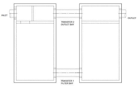
The type of MTD will also impact the parallel layout. For membrane or media filters such as Contech’s parallel Offline Peak Diversion StormFilter system, transfer pipes are set at the filter bay floor elevation to disperse the WQ flow through each filter bay and allow the activation head to build evenly. The outlet bay of each vault is designed to essentially act as a single outlet bay. The outlet bay will receive the treated flow once the cartridges activate and the treated water is released through the flow kit. During the peak storm event, water will bypass over the external weir and through the outlet bay. The peak flow will externally bypass the filter bay where the cartridges are housed, preventing any settled particles from being resuspended and discharged downstream.
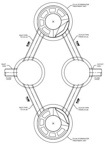
The parallel Offline Peak Diversion StormFilter system has a single external weir. However, for an online parallel HDS system, such as Contech’s Parallel Cascade Separator system, each unit would have an individual weir. To ensure the parallel HDS units are bypassing peak flow as a single system, the internal weir elevations should be set accordingly. Whether the system is online (internal bypass) or offline (external bypass), the outlet invert typically governs the weir elevation, which further reinforces why the elevations are a key part of a parallel MTD system.
As with any MTD design, it is important to keep in mind the potential hydraulic impact, such as a filter cartridge’s required driving head or the head loss through an HDS device. Contech is happy to assess removal requirements, site layout and hydraulics to ensure that the MTD configuration selected is the best fit for each specific site.