Evaluation of Media-Based Stormwater Filtration Systems
By James H. Lenhart, P.E., D.WRE; Vaikko Allen; and Jeremy Gray
Published: April 2018
Overview
There are an increasing number of commercial and structural media-based filtration systems available to engineers and regulators to meet the need for effective and space-efficient stormwater treatment. As part of the due-diligence process, these individuals must understand and evaluate the design, functionality and ongoing operational requirements of the systems. This paper addresses fundamental media filtration evaluation criteria that, when taken together, provide a framework for comparing and contrasting different stormwater filtration systems. Consideration of these criteria is recommended prior to specifying or approving a system.
To perform a successful evaluation of media-based stormwater filtration systems, the following key elements should be considered:
System hydraulics
Media hydraulics
Media type
Structural considerations
Consistency with applicable regulatory requirements
System Hydraulics
Hydraulic analysis of a system investigates the movement of flow through the system with quantification of flux rates, head loss, hydraulic grade line impacts and velocities. At a minimum, the following three steps should be part of the evaluation process:
1. Evaluate the hydraulic grade line (HGL) at the design treatment flow rate. Typically, a backwater calculation from the point of a downstream control should be performed to ensure the system can convey the peak water quality design flow rate. This analysis should include head loss through porous media (filter head loss) and pipe entrance, exit and barrel losses. As an engineering assumption, one should assume the filters are completely occluded and the unit is in complete bypass.
2. Check scour velocities in tanks and pipes. Velocities should be evaluated with particular reference to where sediments are deposited or where high-energy flows can dislodge or scour the filtration media. For example, at the point where the inlet pipe discharges into the filter bay, there must be sufficient energy dissipation to minimize scour. Super critical flows in the inlet pipe will cause a hydraulic jump in the system which will release a large amount of turbulent energy.
3. Ensure high flow bypassing. Bypass configurations can be online, meaning that peak flow rates are routed through the pollutant storage or treatment zone, or offline, where peak flow rates are routed around the pollutant storage and treatment zones of a system. Where possible, offline configurations are preferable, because they minimize the potential for resuspension of previously captured materials. In particular, areas with NRCS Type II and Type III storms require generating a higher ratio of peak conveyance flows as treatment flows will be more susceptible to washout and should be designed in an offline configuration.
Media Hydraulics
Passive stormwater filter media options range widely in gradation, bed thickness and design hydraulic loading rate. At one end of the spectrum are membrane filters relying on very large surface areas and very low flux rates; at the other end are depth filters with greater hydraulic loading rates and filtration happening throughout the depth of the bed. At a minimum, the following steps should be part of the evaluation process:
1. What is the fundamental filtration process? There are two processes commonly used in media filtration for stormwater. First is cake filtration, which is commonly used in sand filter and bioretention cells. Specific flow rates for cake filtration commonly rate from 2 to 12 inches per hour (0.021 to 0.125 gpm/ft2). The flow is commonly controlled by a fine media that develops a sediment cake on top which serves to effectively remove suspended solids. In some cases, biomass and/or additives can enhance the removal of soluble pollutants such as metals and nutrients. Some commercially available stormwater filters utilize a membrane or fabric with a very small apparent opening size and a very large area to remove particulate pollutants at the membrane surface.
The second mechanism is depth filtration, which uses much higher specific flow rates (1-2 gpm/ft2). This works by using a bed of coarse media that allows for the removal of solids by straining, impingement, electrostatic attraction and settling within laminar zones surrounding media particles. The media also may be enhanced with additives for the removal of soluble pollutants.
2. Evaluate the specific flow rate (q) through the media. The specific flow rate, or flux, is most commonly expressed in units of flow per unit area or gallons per minute per square foot (gpm/ft2). Given the specific flow rate (q) times the surface area (A) of the filter, the total flow rate (Q) can be calculated (Q = qA). A good reference point is rapid sand filtration with rates of about 4 gpm/ft2. In general, the higher the rate, the higher the head loss. Finer media typically are more efficient for total suspended solid (TSS) removal as well as other pollutants, but have high head loss characteristics. Coarser media can handle higher flow rates but are less efficient in TSS removal. Claims of high filtration rates with high pollutant removal capabilities and low head loss are highly suspect. As a reference point, 1 gpm/ft2 = 96 inches per hour.
3. Compare the design-specific flow rate to specific flow rates in lab and field studies. The specific flow rate of a media has a significant impact on the performance of a filter, with greater specific flow rates resulting in higher velocities through the media and poorer performance. Therefore, it’s important to ensure that the specific flow rate of the proposed design matches the specific flow rate associated with performance data. For proper filter design, this is an absolute factor. Also, evaluate different model sizes of the proposed BMP to help determine if any physical parameters (wet volume, filter surface area, sedimentation area, etc.) need consideration when evaluating alternate sizes and configurations. Given the same driving head, the specific flow rate should be the same. If the specific flow rates vary with model size, this should raise questions.
4. Consider the thickness and head loss of the media. Darcy’s Law (q = hKA/L) states that flow rate (q) increases with increased head (h), surface area (A) or K (hydraulic conductivity); and decreases with an increased bed length (L) as measured in the direction of flow. The thickness of the media coupled with the specific flow rate determines the amount of contact time between the water and the media. The longer the contact time, the more effective pollutant removal will be, particularly when soluble pollutants are being removed through reactive processes. Thicker media beds will have higher removal rates but will increase head loss. Thicker media beds also will increase media and maintenance costs.
For porous media such as perlite, TSS removal efficiency increases with thickness, because there’s more opportunity for particles to be captured as water follows a tortuous path through interstitial pores. For fine media such as sand, the majority of the TSS capture is at the surface, and media thickness has less influence on TSS removal. Observations and studies of sand filters show that the majority of fine solids removal occurs within the first 2 to 3 inches of bed thickness. In general, Darcy’s Law applies to flow through porous media. However, for many filtration systems with high conductivity and a relatively short bed, Darcy’s Law does not behave with the same accuracy as in a groundwater application. Another confounding factor of stormwater filters is that conductivity declines over time as the media loads with solids. Toward the end of the filter life, K approaches zero asymptotically.
5. Calculate contact time. Compare the calculated contact time with the contact time used in lab or field studies. For example, if the flow rate is doubled and the thickness is reduced by half, the contact time is one fourth. This will have a direct impact on pollutant removal effectiveness. It’s important to check the contact time of the design and the test data presented. Equation 1 can be used to calculate the contact time for a radial flow cartridge.
t is the contact time (seconds) R is the outer radius (feet) ro is the inner radius (feet) p is the porosity of the media Q is the flow rate (ft3/sec) h is the height (feet)
One should also look at the flow paths through the filter. Is there a uniform pressure distribution across the media? A non-uniform pressure distribution results in differential loading of the filter and non-uniform contact time.
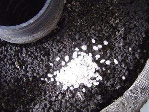
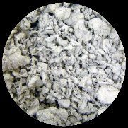
Photo 1. Perlite media, normally crystal white, is occluded with fine sediments.
6. Consider fouling and occlusion of the media. Fouling is a general failure at the surface of the filter caused by the growth of biological films in association with accumulations fines, organics and nutrients. Occlusion is more associated with the progressive accumulation of solids which reduces and ultimately stops flow through the filter. Occlusion can be at the surfaces or a result of filling the pores of a depth filter. This will ultimately control the specific flow rate through the media. One critical aspect is the texture of the surface of the filter. In general, finer media can remove finer particles but have a much higher clogging factor (see Photo 1). Sand can retain about 1.1 pounds of dry sediment per cubic foot before it rapidly clogs and fails (Lenhart and Calvert, 2007), whereas a coarser perlite media can retain about 6 pounds of sediment per cubic foot.
Filtration media that is effective in trapping fine solids will accumulate a thin layer of solids on its surface (schmutzdecke) that begins to occlude the filter and reduce the flow rate. An accumulated layer as thin as 1 millimeter will control the filtration rate and reduce the specific flow rate to very small amounts (< 0.1 gpm/ft2). For example, a horizontal sand filter that builds up a schmutzdecke demonstrates this. Without cleaning mechanisms to prevent surface clogging, this problem becomes endemic to all filtration systems. The following are two important aspects to consider regarding the filter surface:
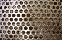
• Know and examine the percent open area of the outer wall of the filter vessel, which includes the filter body and any internal mesh (see Photo 2). The lower the percent open area, the more susceptible the housing is to surface clogging and failure. If the surface of the filter is exposed to light, algal growth can rapidly clog the filter surface.
• Understand the capability of the technology to prevent surface fouling by sediments. It is a fact that effective filters will eventually clog with sediments; the only question is how long that will take. Clearly, if a filter has no active mechanism to remove accumulated sediment from a filter surface, its life will be less than a filter that does.
Photo 2: A filter screen is used to retain media. The total percent open area (17 percent) equals the screen percent open area (43 percent) multiplied by the fine mesh percent open area (40 percent).
Pretreatment by settling will help, but research indicates that most fouling is by fine sediments, organic matter and bacterial growth, all of which are difficult to remove by pretreatment employing rapid settling. In fact, research at Monash University in Melbourne, Australia, (Siriwardene et al, 2005) indicates that particles of 20 µm or smaller cause clogging of sand filters.
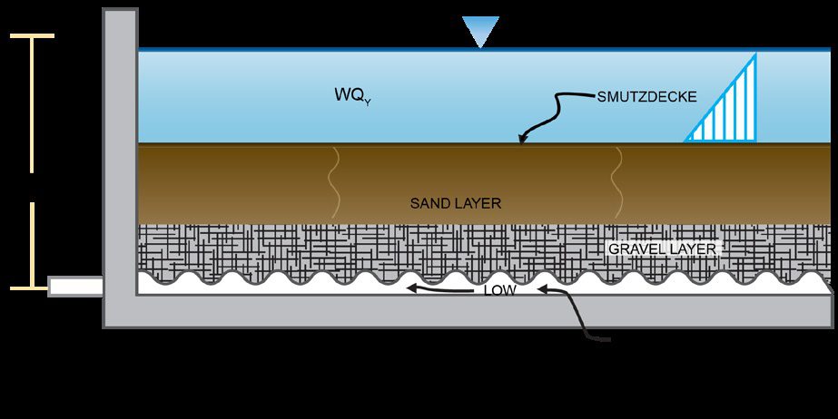
Figure 1. The hydraulic profile of a saturated flow horizontal bed filter. The total system head is measured from the free water surface to the invert out.
7. Compare a horizontal bed with vertical filters. A horizontal bed filter operates by ponding water on its surface such that the driving head causes the water to percolate through the media (see Figure 1). Depending on how it’s designed, the flow through the media may be saturated or unsaturated flow.
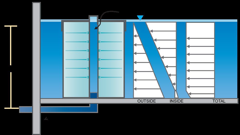
Figure 2. A radial flow, gravity-driven filter cartridge. The mean pressure head is 1/2 of the water depth because of a triangular pressure distribution, unless they’re operating with pressure on the outer surface as well as suction on the inner surface to Figure 2. A radial flow, gravity-driven filter cartridge. The mean pressure head is 1/2 of the water depth because of a triangular pressure distribution, unless they’re operating with pressure on the outer surface as well as suction on the inner surface to create a uniform pressure distribution across the filter media bed (see Figure 3).
Figure 3. A radial flow, siphon-driven filter cartridge where a suction head on the interior and driving head on the exterior sums to a uniform pressure head equal to the depth of the water.
One characteristic of horizontal bed filters is that all collected sediments will impact the surface of the filter, thus reducing longevity, whereas vertical filters allow much of the sediment to be deposited on the floor, away from the filter media. Horizontal bed filters have the benefit of a constant pressure head (equivalent to the depth of water) over the entire filter surface. Vertical filters have a reduced driving head (equivalent to half the depth of water; see Figure 2).
Media Type
A variety of different filter media have a long track record of successful use for stormwater filtration, including sand, peat and compost. Recently, perlite, zeolite, carbon and other “exotic” media have expanded the choices for targeting specific pollutants.
Consider the physical properties of the media used for sediment removal. Most filter media remove solids by mechanical processes. The gradation of the media, irregularity of shape, porosity and surface roughness characteristics all influence TSS removal characteristics. Finer media are more effective at removing TSS than coarse media, but they create higher head loss and have higher clogging factors. This tradeoff is a fundamental consideration. Finer media with a less uniform gradation also typically results in a lower flow rate at the same amount of driving head.
Understand the chemical properties and mechanisms used to remove stormwater pollutants. Many types of pollutants such as nutrients, metals, and oil and grease are insoluble or free-form, and they can be removed through chemical and/or biological processes. Common processes are cation exchange, precipitation, chelation and adsorption. When claims are made for soluble pollutants, there needs to be a documented process by which these reactions take place. In addition, these reactions have limits in terms of sorption capacity and reaction kinetics. For example, media may have a sorption capacity of “X” mg/kg of media. Given the mass of the media, the total mass of pollutant that can be removed can be calculated and then compared with what’s generated from the site. Reaction kinetics also cause a slowing of pollutant removal rates as media saturation increases and/or pollutant concentration decreases.
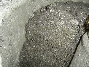
Photo 3: A pulp-based absorbent, although effective for soaking up oil spills, will rapidly decompose when used as a stormwater filtration media.
The reviewer also should consider if the media can add constituents to runoff. For example, organic media can elevate ortho-phosphorus in filter effluent as it leaches from the media. In nutrient-limited watersheds, this is undesirable, and an alternate should be selected. Other media can raise or lower pH. In all cases, media should be tested for aquatic toxicity and rejected if shown to leach chemicals or degrade in forms or quantities that impair downstream biota.
Evaluate whether the properties of the media will change over time. Stormwater is a complex mixture of sediments, nutrients, organic matter, bacteria and other pollutants. Many times, media may perform well in the short-term, but in the long-term may be compromised by biological decomposition, bacterial slimes or simple decomposition by continuous saturation in water (see Photo 3).
For example, cellulose-based media such as treated pulp, corn cobs or rice hulls will decompose when exposed to these elements. Media that swells or shrinks on wetting and drying cycles also can be problematic because it changes the bed properties. Swelling media can prevent design hydraulic loading rates from being reached and can damage media containment equipment. Shrinking media can open up preferential pathways in the media bed and lead to short-circuiting. Filter media should be free draining. Permanently submerged media can lead to anoxic conditions, causing anaerobic decomposition and release of many of the trapped pollutants.
Check media availability, cost and quality. Media that is only available in small production quantities or does not meet all specifications should be avoided. Some systems can accommodate multiple-media options either mixed or layered within the same bed or as alternative bed materials. Variable-media systems have the versatility to fine-tune media to site-specific pollutants as well as adapt to future improvements in media effectiveness. The media provider should be able to demonstrate media QA/QC history to know the product is meeting specification (Hills, 2017).
Structural Considerations
Structural integrity is critical. Most subsurface stormwater filtration systems are designed to handle traffic loads, so it’s important to evaluate the structure for integrity and design life. Make sure the structures are reviewed by structural engineers to ensure expected traffic loads can be handled.
Water tightness is required by many agencies.Evaluate vertical and horizontal joints for design integrity. Vertical joints are more difficult to control because of differential settlement. Some agencies require a water-tightness test prior to acceptance. All joints below the permanent pool elevation need to be watertight.
Buoyancy measures need to be considered. In areas of high groundwater, take measures to prevent system floatation.
Constructability considerations are important. Many times what appears simple on the plans can be difficult during construction. Consider construction loads, backfilling, etc. Does the contractor have a track record of constructing and installing similar facilities?
Consider materials of construction. Stormwater runoff can be very corrosive. The presence of numerous nuts and bolts, differential metals contact, pivot points and hinges, and galvanized parts are all potential candidates for corrosion and ultimate failure.
Maintenance Considerations
Proper operation and maintenance is critical to success and should be considered when evaluating stormwater filtration systems.
Product Support
Does the manufacturer warranty the product?Typically there’s a minimum one-year constructability warranty on the structure and components.
Does the manufacturer provide support to the installing contractor or owner? Filtration systems are more effective and more complicated than simple gravity settling or vortex separation devices. It’s important that, if requested, the manufacturer be able to supply the contractor with installation support for complex structures. Furthermore, the manufacturer should be prepared to offer ongoing, long-term owner support to ensure proper operation and maintenance.
Other Considerations
To establish credibility of performance, installation, operation or maintenance claims, it’s wise to check references and speak with other agencies where the facilities have been installed. Remember, because of the variable nature of stormwater runoff, all types of facilities—ponds, swales, filters, settling devices and others—will have examples of poor performance, but overall the assessment should be positive. Checking manufacturers’ claims is critical. A large number of reports do not necessarily imply a system is well tested or verified.
Integrate all the considerations into an overall assessment of how a proposed system matches performance data from prototypes. This is a critical review. If the design flow rates, media thickness, etc., do not match the studies, increasing the size of the facility to match the test values is warranted.
Make sure the data presented are consistent with pollutant concentrations and characteristics typically associated with stormwater runoff. Common claims that illustrate inconsistencies include the following:
• Performing a study with sand or grit and equating the percent removal to the removal of silts and clays in the field.
• Performing a study with very high concentrations of oil in water to assess oil and grease (O&G) removal and then using these data to claim high percentage removals on stormwater runoff, which has much lower concentrations of O&G.
• Performing studies conducted at a fraction of the design flow rate. (If a filter is designed with a high specific flow rate, it should be tested at that rate.)
Evaluate lab data vs. field data. Lab data are collected under controlled conditions and can provide a lot of insight on filter behavior. Studies successfully executed at the laboratory level include analysis of TSS removal at different flow rates and hydraulic behavior. Properties that can’t be evaluated in the laboratory include fouling characteristics, maintainability, and pollutant removal characteristics with complex hydrology and water chemistry. Laboratory data provides rapid data collection and good insight to filter performance but should not be used as a sole method to judge performance.
Programs for Filtration System Verification
New Jersey and Washington have implemented statewide programs to evaluate filtration technologies (and other technologies) to ensure that the technology can meet the water-quality objectives. The programs, known as the NJCAT and TAPE processes, are well documented and available on the internet.
In short, these programs outline monitoring protocols, treatment goals, reporting standards and other criteria that all new BMPs must be subjected to for final verification and approvals.
Conclusion
These factors are meant to serve as guidelines for the preliminary review of new products. If this review meets the satisfaction of the reviewer(s), the next consideration should be pilot facilities that lead to system acceptance. If a submittal does not appear to meet the aforementioned criteria, the design engineer or reviewer needs to seek clarification or redesign.
REFERENCES
• Siriwardene, N.R., A. Deletic, and T.D. Fletcher, 2006. “Preliminary studies of the development of a clogging prediction method for stormwater infiltration systems,” Proceedings, 4th International Conference on Water Sensitive Urban Design, Melbourne, Australia, April, V1.211-V1.218.
• Lenhart, James H., P.E., and Paula P. Calvert, 2007. “Mass loading and mass load design of stormwater filtration systems,” Environmental Water Resources Institute, Proceedings, April 2007.
• M. Hills, A. Macleod, J. Lenhart, 2016. “Ensuring bioretention system performance success: Guidance for the verification of bioretention media via quality assurance and control testing,” World Environmental and Water Resources Congress 2016, pp. 364-370.
Authors
James H. Lenhart, P.E., D.WRE
Jim Lenhart is the Chief Technology Officer for Contech Engineered Solutions. He was founder of Stormwater Management Inc. and was also owner of Stormwater Northwest, where he consulted with companies that provide products and services in stormwater-related markets. Lenhart has authored more than 50 papers on the subject of water quality and stormwater treatment. He is a professional Agricultural and Environmental Engineer with more than 25 years of experience in consulting engineering, and research and development. He served as an adjunct instructor of Civil Engineering at Portland State University, where he taught hydraulics and water resources engineering. Lenhart currently is an active member of the Water Environment Federation, the Water Environment Research Foundation, ASCE EWRI, and serves as Chair of the Urban Water Resources Research Council. Lenhart holds a BS in Plant Sciences, a BS in Agricultural Engineering, an MS in Water Resources Engineering and is a Diplomate of the American Academy of Water Resources Engineers.
Vaikko Allen
Vaikko Allen currently serves as Director of Stormwater Regulatory Management for Contech Engineered Solutions, where he assists regulators, engineers and environmental organizations in the development and implementation of stormwater regulations. Throughout his 20 years of stormwater management experience, he has managed stormwater system monitoring programs and development initiatives, and participated in numerous workgroups, providing technical guidance on TMDL implementation, hydromodification, low-impact development strategies and industrial stormwater compliance. Allen holds a bachelor’s degree in Environmental Science and Policy from the University of Southern Maine with a concentration in Water Resources.
Jeremy Gray
Jeremy Gray is the Filtration Product Manager for Contech, directing the strategy, leadership, and execution of the Jellyfish and StormFilter product lines. Since starting with Contech in 2004, he has held a series of roles with increasing responsibility within Contech’s Stormwater segment. These experiences managing projects across several stormwater markets with varied treatment strategies have given him the vision to assist in the development and design of Contech’s filtration products overall and on hundreds of individual projects. Gray has a B.S. degree in Mechanical Engineering from Tufts University.
Quiz Instructions
Online quiz for this article is not active and PDH credit is no longer available.
This article is being maintained for informational purposes only.
Learning Objectives
Understand media-based stormwater filtration system hydraulics