6 Red Flags To Watch Out For When Designing Hydrodynamic Separators
Hydrodynamic Separators (HDS) – often referred to as oil-grit separators, swirl devices, or vortex separators – are best management practices often used to remove sediment, hydrocarbons, trash and debris from stormwater runoff. HDS units are regularly used as either standalone treatment devices or pretreatment
systems to detention, infiltration, rainwater harvesting and green infrastructure systems. In any application, there are a few red flags that the designer should keep in mind.
- Above Grade Installations - Traditional HDS units are designed to be installed below grade with soil supporting the walls of the structure. When HDS units are installed above grade, custom structural analysis is required.
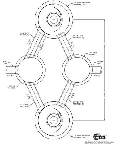
- High Flows - In some cases, particularly sites with very large drainage areas, the flow rates exceed the hydraulic capacity of precast HDS units. In these instances, cast-in place units can be designed to treat the large flows. Alternatively two units can be used in parallel with a flow splitter manhole upstream as seen below.
- Structural loading - Most units are designed to meet HS 20 loading unless otherwise specified. HDS units can be designed to accommodate higher loadings, for example; airport, fire lane, etc. Often this will require a custom structural analysis to be performed and should be evaluated early in the design phase.
- Inlet and Outlet Pipe Diameter - Inlet and outlet pipe size can often dictate which model size is needed for a specific project. Each HDS device has a maximum pipe diameter that can be accepted for each model size.
- Pipe Orientation - All HDS units have limitations on where the inlet and outlet can connect to the device. For example, some HDS units like the Vortechs product shown below rely on the placement of the inlets to activate the swirl. In this example, there are four possible locations for the inlet pipe. If two inlet pipes are desired, their location must be so that they both introduce flow in the same direction.
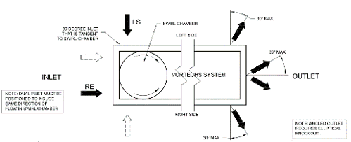
Additionally, pipe locations into the units should be examined closely to confirm that the knockouts do not interfere with each other, the joints or the top slab. This could impede manufacturability or jeopardize the structural integrity.
- Elevations – Each product and model size requires different minimum distances from grade to the outlet invert. It is important to keep in mind that the outlet pipe is typically what drives the layout of the system.
Much of what was discussed in this post highlights key features of HDS units that should be addressed early in the project design phases. Things like unit selection, location, and how it is configured with the rest of the drainage network can impact many of the downstream phases in the project life cycle. These discussion points are also features that can be easily overlooked, and addressing or identifying seemingly simple items can save both time and money in the long-run.