
Where in the Deck? ... Drain
Have you ever heard of Theodore Cooper? Well, if you work in the railroad industry, you might say, “Yes, I have.” If you are a civil design engineer and member of the “Order of the Engineer” and wear a stainless-steel ring on the little finger of the working hand, you might say, “No, I have not.” However, the vast majority of Civil Engineers have heard of E80 Cooper loading.
Theodore Cooper graduated from Rensselaer Polytechnic Institute in 1858 and went to work for the Troy and Greenfield Railroad and worked on the Hoosac Tunnel in Massachusetts. In 1861, he entered the Navy and spent time on a gunboat in the South Pacific then as an instructor at the U.S. Naval Academy and resigned in 1872 with the rank 1st Assistant Engineer. He then went to work for Midvale Steel Works and succeeded James Eads, the designer of the Eads Bridge (St. Louis), from 1872-1875. His career in bridge design spanned from 1872 to retirement in 1907. (Wiki)
Between 1885 and 1902, Cooper published several important works on railroad and highway bridge design. His theories strongly influenced the adoption of wheel-load analysis for railroad bridges. The career of this distinguished and celebrated engineer who was twice awarded the Norman Medal by ASCE ended in tragedy when the monumental Quebec Bridge for which Cooper was consulting engineer, collapsed while under construction in 1907, resulting in 75 fatalities. (Wiki)
The Order of the Engineer ceremony was modeled after Canada’s Ritual of the Calling of the Engineer. That ceremony began in 1926, using a wrought iron ring and an oath written by poet Rudyard Kipling. As a common legend/myth goes, the iron from the first rings was collected from the wreckage of the Quebec Bridge. (NSPE)
In 1894, Cooper developed a system of calculation and standards for the safe loading of railway bridges. Cooper’s loading system was based on a standard of E10, meaning a pair of 2-8-0 type steam locomotives, pulling an infinite number of rail cars. Each locomotive was given an axle loading of 10,000 pounds for driving axles, 5,000 pounds for the leading truck and 6,500 pounds for the tender trucks. Each trailing car was given an axle loading of 1,000 pounds per foot of track. During, the 1880s, railway bridges were built using an equivalent rating of E20. By 1894 when Cooper presented his standard, he recommended a standard of E40. By 1914, the standard had increased to E60. By the mid-1990s, the American Railway Engineering and Maintenance-of-Way Association (AREMA) was recommending E72 (7.2) times the E10 standard for concrete structures, and E80 for Steel Structures. (Wiki)
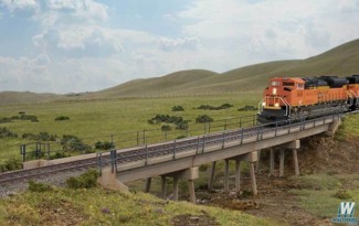
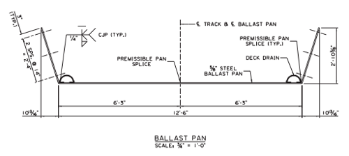
When you think of train bridges, most people imagine a steel truss bridge with railroad ties on bridge beams, but a growing number of railway bridges around the world are now using steel pan and concrete structures that allow the design engineer to create a trough to hold and retain ballast stone. This provides a continuous ballast-rail and tie track system across the span.
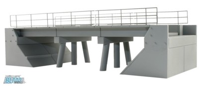
If you have ever walked across a steel railroad truss bridge, carefully stepping from one railroad tie to the next and looking cautiously down between the railroad ties and beams to the roadway, stream or river below, you quickly understand that drainage is not an issue with this type of bridge. When you build a railroad ballast trough style bridge for either a heavy cargo railroad or light passenger railway, you can easily see that a way to drain the railway ballast is needed. The system that you use needs to collect the water to minimize the amount that can pond on the deck and quickly usher the water off the bridge. Trains do not like steep slopes, so these bridges are often designed from zero to very slight gradients. The designer must also mitigate the water from running off the ends of the bridge which can lead to erosion problems at the abutments.
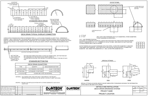
Corrugated metal pipe (CMP) has long been a staple in the use of culverts for the railroad industry. CMP can handle the heavy E80 Cooper loading, and extreme vibratory conditions of trains. CMP is strong, lightweight, durable, versatile and cost-effective, making it the perfect candidate for use in a railroad application. However, while placing a round perforated pipe on a rigid flat steel pan or flat concrete bridge deck would probably work, it would be nice if the bottom of the drainage conduit was flat. This is where DECK DRAIN works fantastically! (8” strip perf and 12” fully perforated examples shown below.)
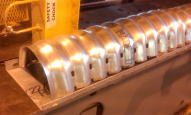
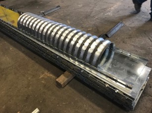
Utilizing a flat perforated bottom pan and semi-circular perforated piece of corrugated metal pipe you can collect the water on the bridge deck and usher it along the bridge to outlet pipe that descends through the bridge deck and into a downspout piping system directing the runoff away from the bridge structure so not to cause any erosion issues.
Standard 8-Inch Deck Drain Detail
Steel Trough Deck (LA DTOD)
Concrete Trough Deck (Metropolitan Council)
![]()
This product is available in various sizes, easy to install and cost-effective. So now you know ……