
Staying Grounded
Last month, I was excited to present in a national webinar focusing on efficient design of storm sewer systems. As part of the content, I shared a pipe technology that can be used as underground storage tanks for contaminated runoff and sanitary sewer – this information sparked several questions in the post webinar survey pertaining to floatation and buoyancy control. It occurred to me that in the world of underground tankage applications, the idea of a specified tank coming out of the ground can be as scary to the designer as a zombie rising from the grave. That said, I would like to share a few tank solutions that I hope you will find beneficial for staying grounded.
For subsurface tanks installed in areas prone to saturated soil due to high ground water or flooding, we must make considerations to ensure floatation does not occur. The analysis for buoyancy can have many aspects depending on the particular design criteria, but generally speaking, the buoyant force created by the weight of water displaced by the tank should be overcome by enough downward force to prevent it from coming out of the ground like a giant zombie. This downward force is created by the soil above the tank along with weight of the tank and any liquid inside of it, but sometimes additional help is needed to keep floatation from occurring.
As an example, consider a basic approach where a sanitary overflow storage tank is completely empty and ground water is up to the crown of the tank - let’s say the tank is needed to contain 11,000 gallons of effluent within an allowable 45’ x 10’ site footprint under two feet of cover in an area of the project where there will be vehicular parking above the tank. One solution would be to utilize a tank fabricated from DuroMaxx® Steel Reinforced PE pipe, which would provide several benefits:
- DuroMaxx® can easily handle the H20 vehicular live loads in the parking area above with minimum cover.
- The HDB rated PE resin is highly resistant to corrosion from hydrogen sulfide gas and other chemicals typically found in sanitary sewers.
- Standard equipment can be used for fast and straightforward installation (no crane is needed).
- DuroMaxx® is cost effective and durable; it will meet a 100 year design service life.
When selecting a cylindrical tank size, it can be beneficial to utilize the largest diameter possible for the site constraints – for example, just doubling the diameter from 42” to 84” will yield four times the open area - this saves cost and reduces the overall footprint size. Therefore, looking at an 84” nominal diameter DuroMaxx® tank, a length of 40’ would provide 11,161.69 gallons (1,492.1 c.f.). Recall that our design calls for 2’ of cover with a parking lot on top for efficient utilization of space. Conservatively, the tank is completely empty, the shear strength of the soil is minimal, and groundwater will fully saturate the soil to the top of the tank. From a quick calculation, we can compare the buoyant uplift force with the downward resisting force:
Buoyant uplift force:
- Weight of water displaced = 1,492.1 cf x 62.4 lbs/cf = 93,107.04 lbs
- A conservative approach is to apply a safety factor here:
- 93,107.04lbs x 1.5 safety factor = 139,660.56 lbs ↑
Downward resisting force:
- Weight of soil above tank less the open area of a 36” top access riser:
(2’h x 8’w x 40’l) = 640 cf – 14 cf access riser open area = 626 cf - Assume soil unit weight of 120pcf = 626 cf x 120 pcf = 75,120 lbs
- Weight of 84” tank = 40 ft x 76.3 lbs/ft = 3,052 lbs
- Total = 75,120 lbs + 3,052 lbs = 78,172 lbs ↓
Therefore, the additional weight needed to counteract the buoyant uplift =
139,660.56 lbs – 78,172 lbs = 61,488.56 lbs
It is possible that additional criteria could be considered in the design such as:
- The class of soil used, the amount of compaction used, and the shear strength the soil. A soil “wedge” design approach rather than a straight column could be utilized - however, this type of approach may not be adequate for multiple tank barrels within close proximity since part of the resisting force “wedges” may overlap.
- If the saturated soil is all the way to the surface, some of the downward force generated by the weight of the soil will be counteracted by the upward buoyant force of the water displaced by the soil. Conversely, if the saturated soil is below the top of the tank, the amount of buoyant uplift force will be reduced.
- Since this is a parking area, there will likely be a surface pavement on top which would help by adding to the resisting force.
All of this said, the primary contributing factors will usually be the soil depth over the tank, the height of ground water above the invert, and an appropriate design factor of safety.
Now let’s look at some options for achieving the 61,489 pounds of additional resistance for our example:
Increase Cover
If it is possible to raise the surface elevation or bury the tank deeper to increase the amount of cover over the top of the tank, that may be an option. For 84” DuroMaxx®, this new cover would need to be 3’-9” to prevent floatation of a fully surcharged empty tank. However, for our example we are limited to 2’ cover. As well, we are also constrained to a fairly small site footprint, so using a smaller diameter is not conducive in this case.
Utilize a Stabilization Pad
Incorporating a reinforced concrete pad at the surface above tank can prevent floatation. This pad should extend at least 2’ past the tank in each direction. Alternatively, a concrete bottom slab could be poured as a foundation for the tank. The bottom slab would have connections cast into it for straps to go around the tank to secure it to the slab.
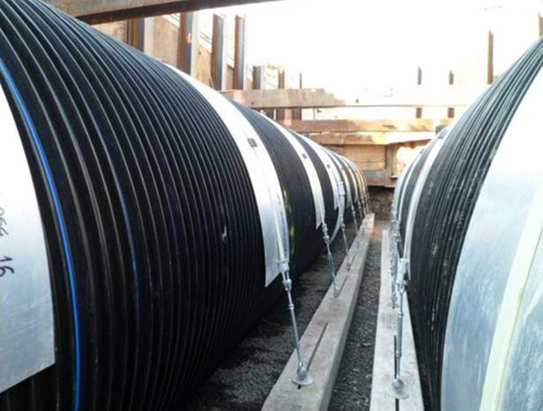
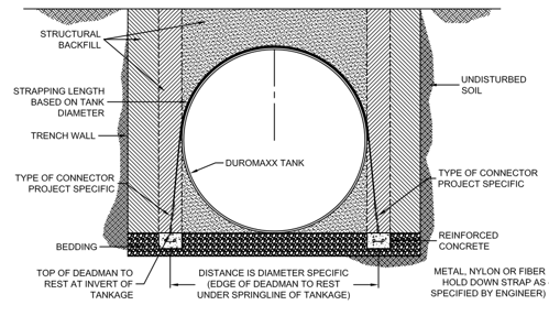
Attach Dead Man Anchors (fortunately, I’m not talking the zombie variety here)
The picture and detail below illustrate this approach in which a beam of reinforced concrete is placed on either side of the tank and connected with straps over the pipe. The weight of the concrete anchors as well as the soil column above them will contribute to resisting the buoyant uplift force. Note that the concrete deadmen should be placed in an offset fashion so that they are outside the pipe spring line of the tank and not under the lower haunches – this allows engagement of the soil column above the anchors.
Use a Stabilized Backfill
Using a controlled low strength material (CLSM) around the top half of the tank is another option. This material should have a minimum submerged unit weight of 70 pcf, a minimum compressive strength of 1,000 psi, and dimensioned as shown below to exceed the buoyant force.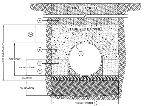

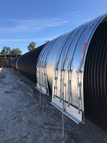
Secure with Nylon Straps & Ground Anchors
This approach utilizes strong nylon straps over the tank which are secured on either side by percussion-driven or helical ground anchors. One company which specializes in this type of system, Platipus Anchors, offers a 2-Ton and 10-Ton pipe anchoring kit which eliminates the need for placing additional fill or pouring concrete to counteract buoyant forces.
So there you have it – some tips and best practices to help with staying grounded on your next buried tank design and avoiding the potential of a zombie apocalypse. Thank you for reading! I hope you will reach out to your local Contech representative as a solutions partner for your next project.