Months of design, pages of specifications, and tens or even hundreds of thousands of dollars may go into the design of a single bioswale, filtration basin or other stormwater treatment system. So why do engineers spend so little time thinking about the flow-control devices that make them work? This article focuses on the design of external stormwater diversion structures—an integral component of a complete stormwater management system.
“First flush” is a concept familiar to designers of stormwater treatment systems and refers to the initial surface runoff of a rainstorm. During this phase, water pollution entering storm drains in areas with high proportions of impervious surfaces is typically more concentrated compared to the remainder of the storm. Consequently, these high concentrations of urban runoff result in high levels of pollutants discharged from storm sewers to surface waters.
It’s impractical to treat an entire large-storm event, but we intend to capture the “first flush” from those storms and the entirety of smaller, more-frequent storms. In contrast, when a site generates a large volume of runoff, stormwater infrastructure should be designed to efficiently convey it all downstream without negatively impacting treatment devices. To achieve this balance, we rely on a type of flow control called a diversion system to handle the high-flow bypass.
Determining the need for a high flow bypass
A high-flow bypass is needed when the peak conveyance flow for your site exceeds the treatment capacity or online bypass capacity of your stormwater quality facility. You may have already discovered a need for a high-flow bypass during the design of your stormwater treatment system. If you haven’t determined your site’s peak-conveyance flow and water-quality flow, calculate the water-quality flow (Qtreat) and peak-conveyance flow (Qpeak) using the approved hydrologic models established by your local agency. If your agency specifies a water-quality volume rather than a peak flow, water-quality volume requirements can be translated into a flow rate.
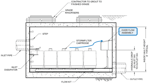
Figure 1. A well-designed online media filtration system.
Online vs. Offline Systems
Diversion configurations can be “online,” meaning peak flow rates are routed through the pollutant storage or treatment zone, or “offline,” where peak flow rates are routed around the pollutant storage and treatment zones of a system.
Many manufactured treatment devices (MTDs) offer online diversion options, meaning they can be configured to allow the entire influent flow to enter the treatment system as well as allow for excess flows above the treatment capacity to internally flow within the device. This innovation reduces the complexity of storm sewer layout and significantly reduces cost, as the contractor can install one manhole instead of three.
 Figure 2. An example of an offline configuration.
In addition, online units are ideal for retrofit applications where an existing drainage line, standard junction manhole or poorly performing device can be replaced without other site disturbance. There are also quality-control advantages to having the weir integral to the treatment system’s internal components. In particular, the device would come with the weir set to the correct height with no opportunity for error by the specifier or installer. The media filtration system in Figure 1 is a well-designed example of this. Engineers who rely on “online” overflows must be careful not to introduce too much flow and risk scouring trapped sediment.
In contrast, a diversion control upstream of a treatment system is called an “offline” system (see Figure 2). Offline systems direct low flows into a treatment system, but have the advantage of preventing peak flows from ever entering these systems, thus limiting the potential for scour.
Caution needs to be taken when designing online systems. Does the flow path in the unit route high-velocity bypass away from sensitive filter surfaces and previously captured pollutants? Do these pollutants stay contained, or are they subject to scour from increased turbulence? Does the unit have adequate internal bypass capacity to convey the design peak-storm event?
Offline configurations often are preferred, because they minimize the potential for resuspension of previously captured materials. For example, areas with NRCS Type II and Type III storms require generating a higher ratio of peak conveyance flows, as treatment flows will be more susceptible to washout and may need to be designed in an offline configuration.
Designing Offline Systems
Although offline systems often are preferred, they still must be properly designed to ensure they don’t allow too much flow into the treatment system as head builds up over the bypass.
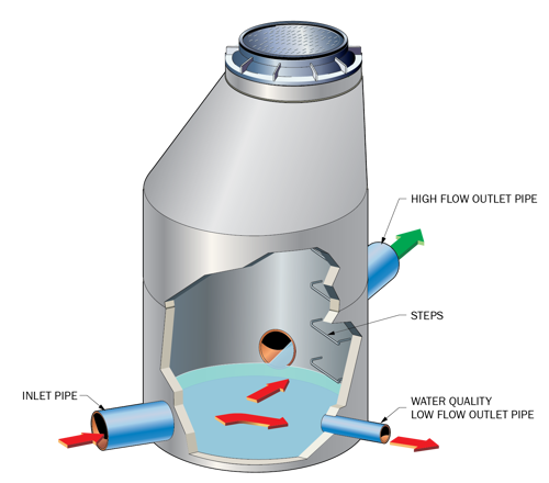
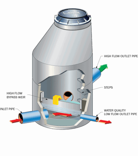
Figure 3. Top, bypassing using pipes at different elevations. Bottom, a weir and orifice combination.
As shown in the left part of Figure 3, a common method used when designing offline diversion structures is to place two outlet pipes in a manhole. The smaller-diameter pipe is placed at a low elevation to direct the low flows (or water-quality flows) to a water-treatment facility. This pipe is modeled as an orifice or culvert to calculate the head required to drive the water-quality design flow through it. After the head requirement is known, the invert of the larger high-flow pipe is placed at the design water-surface elevation.
Although inexpensive, this type of configuration may not function as intended. Based on field observations, negative issues include the following:
• If the small pipe is inline with the larger pipe, high-velocity inflow will increase the discharge through the small pipe, and hydraulic control is lost.
• Since both pipes act as an orifice, during high-flow events, flows to the water-quality facility may exceed design values.
• What’s actually constructed in the field isn’t always what the engineer designed. This type of design isn’t field adjustable to compensate for construction error.
A more-sophisticated and effective method of designing a high-flow bypass uses a weir as shown in the right side of Figure 3. As flow increases on the low-flow pipe, which may have an orifice, it will begin to submerge. It builds enough head until the flow reaches the water-quality design value. The overflow weir crest is set to this elevation, allowing excess water to spill over the weir into an outlet pipe.
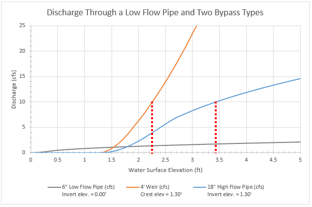
Figure 4. A graph shows calculated discharge through different flow-control devices.
Figure 4 illustrates how these two designs compare. Assume a water-quality flow rate of 1.0 cfs and a design peak-flow rate of 10 cfs. An 18” conveyance pipe would be suitable at 1% slope, therefore a designer may use a 48” manhole to provide bypass functionality. Assuming a 6” low-flow pipe is selected, an estimated 1.30 feet of head would be required to reach the treatment rate. It’s first modeled with the 18” high-flow pipe, and then it’s modeled with a 4-feet-long weir.
In this example, the weir is able to bypass the peak flow at a calculated Hydraulic Grade Line (HGL) of 2.25 feet, as indicated by the dashed red line to the left. At this stage, the treatment system would receive an estimated 1.33 cfs (33% beyond the design rate). On the other hand, the high-flow pipe design would require an HGL of 3.43 feet to bypass the peak flow, as indicated by the dashed red line to the right. At that elevation, the treatment system would receive 1.68 cfs (68% above design)—double the exceedance caused by the weir. Why is this happening?
Note the flat characteristic of the orifice vs. the exponential characteristic of the weir. This combination is desirable because at higher stages the flow into the water-quality facility is relatively independent of the HGL above the design head on the orifice. This characteristic results because the flow through an orifice is proportional to the square-root of the head, whereas the flow over a weir is proportional to the head raised to the 3/2 power. The relevant equations are:
Equation 1: Orifice:
Q=CA√2gh
where Q is the flow in cubic feet per second, A is the inside area of the orifice in square feet, g is the gravitational constant (32.2 ft/s2), and h is the head on the orifice. C is the discharge coefficient.
Equation 2: Weir:
Q= Clh3/2
where l is the length of the weir in feet, h is the head on the weir in feet, and C is approximated at about 3.3.
Adjustable Weir Plates
A final issue is the potential effect of minor deviations in the construction of a diversion manhole from specified elevations. These could be caused by inaccuracies in existing elevations taken from surveys, manufacturing tolerances or construction error, among others. Continuing the example above, imagine the bypass crest was set at an elevation three inches lower relative to the low-flow pipe than specified. The treatment system would only be functioning at about 80% capacity, wasting valuable money spent on capacity and potentially not meeting regulatory requirements.
Fixing this error post-construction would be costly. The buried manhole would need to be excavated, a grouted pipe saw cut, etc. In contrast, an adjustable weir could solve this problem in minutes as shown in Figure 5. Adjustable weirs typically allow adjustments of 6” up or down from the specified elevation in the field. Making adjustments is quick and easy. Adjustments are made by loosening the screws, sliding the weir up or down, and re-tightening the screws. Adjustable weirs also provide a unique advantage on redevelopment projects where the treatment flow rate is increased slightly to account for newly developed drainage area, assuming the treatment device has the capacity to handle the increased treatment flow. With the unique advantages provided by adjustable weir plates, they’re becoming more popular on stormwater projects.
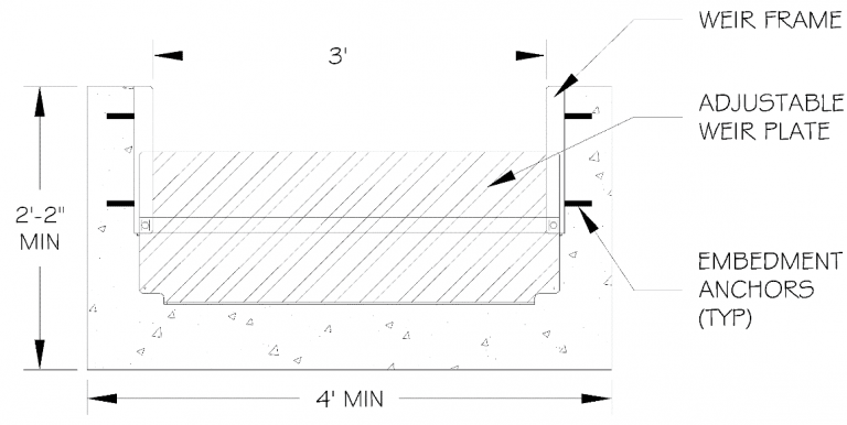
Figure 5. An adjustable aluminum weir installed in a concrete weir wall. The weir crest elevation can be adjusted up or down by 6 inches from the design elevation.
Key Design Considerations for Offline Systems
There are five key steps that should be considered to determine the orientation of a diversion structure and the proper placement of the weir as well as inlet and outflow pipes.
1. Set the low-flow pipe diameter and invert elevation so the pipe has adequate capacity to convey flows from the diversion structure to the treatment system during the design storm. If this pipe is greatly oversized for the design storm, the excessive flow could unintentionally be directed to the treatment system during peak-storm events. This will reduce the treatment system’s effectiveness and negate the purpose of the diversion structure. To avoid this potential issue, an orifice plate may be used to restrict the flow to the treatment system; alternatively, setting the pipe so it flows full during the design storm simplifies the system and installation.
2. Using the pipe diameter and invert elevation determined in Step 1, determine the hydraulic grade line in the diversion structure when the design storm flow (Qtreat) is being directed to the treatment system. (Note: You may need to consider backwater effects on the system.)
3. Specify the location of the weir in the diversion structure so the weir is at the same elevation as the hydraulic grade line at Qtreat.
4. Calculate the hydraulic grade line in the diversion structure at the peak hydraulic flow. (For example, the flow resulting from the 10-year storm event.) Verify that the peak hydraulic grade line doesn’t cause operational problems in the collection system upstream of the diversion structure.
5. Determine the size of the manhole or vault required to accommodate all flow lines entering and exiting the structure.
Summary
It’s impractical to treat an entire large-storm event. When a site is generating a large volume of runoff, stormwater infrastructure should be designed to efficiently convey it all downstream without negatively impacting treatment devices, making the proper design of external stormwater diversion structures an integral component of a complete stormwater management system.
Author
Seth Sokol, P.E., is a Senior Stormwater Design Engineer and Team Lead at Contech Engineered Solutions. He holds a Bachelor of Science in Engineering degree in Civil and Environmental Engineering from Duke University and is a registered Professional Engineer in the State of Oregon; email: [email protected].