
- Pipe
- Bridges & Structures
- Walls
- Stormwater Management
- Erosion Control
- Start a Project
- Knowledge Center
- Technical Guides
Buried bridges can be described as a buried structure with a clear span of 20 feet or greater that supports an embankment and engages the passive support of the backfill material surrounding it. There are many different types of buried bridges used in highway construction. Some solutions are constructed from concrete; others utilize steel or aluminum in their designs. Buried culvert pipes utilize the same passive soil support and share many similar issues that impact the service lives of these structures.
Buried structures frequently offer advantages over traditional slab bridges. Pavement design and maintenance are simplified with buried structures, as the same pavement design used in the roadway profile can typically be utilized over the buried structures. Buried pipes and bridges often provide accelerated design and construction schedules as compared to conventional bridges. Because buried structures help dissipate surface live loads, they frequently can utilize full inverts or shallow foundations and eliminate the need for piling or other deep foundations commonly used in conventional bridge construction. All of these advantages often lead to lower installed costs as well.
In addition, buried pipe and bridge structures typically require less maintenance than conventional bridges. However, as with any structure, there are some design elements that should be considered to help decrease the ongoing maintenance of the structure and extend its service life.
One of the most important design decisions that affects the expected service life of pipe or structural plate drainage structures is the material and coating used for the structure itself. Culvert pipes 60” in diameter or less can be manufactured using concrete, steel, aluminum, steel-reinforced polyethylene (SRPE) or several different grades of plastics. Most plastic pipes are not available in diameters greater than 60”. Steel pipes are available with many different coatings such as galvanized, aluminized and polymeric coatings.
For larger-size structures used for culverts and virtually all bridge structures, the commonly used materials will be steel, aluminum and concrete. There are many resources that can be utilized to establish the service life of these materials based on the environment in which they’re to be used, but, in general, galvanized steel can provide a 50-plus-year service life in most inland environments, polymer-coated steel can provide a 75-plus-year service life in a wide range of environments, aluminum can provide a 75-plus-year service life in most environments (including brackish and saltwater applications), and concrete can provide a 75-plus-year service life in a wide environmental range. The service-life expectations of structures constructed from any of these materials can be extended to 100 years or more by understanding the common limiting factors of these structures and making design decisions to address those factors.
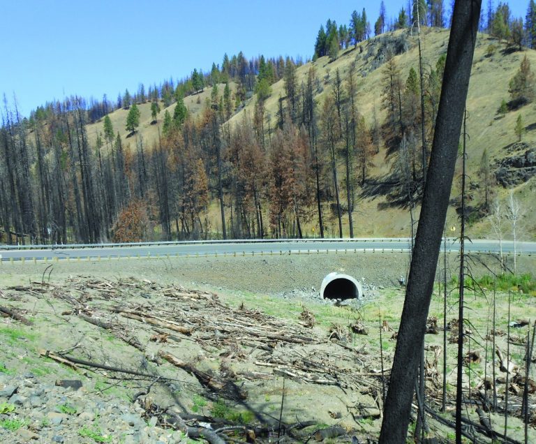
Although use of a conventional pavement over the structure eliminates joints within the roadway, pavements can develop cracks through time that can allow road salts and other de-icing agents to penetrate the pavement and be carried down to the crown and backfill of the buried structure by the surface water from the roadway. Through time, these salts can accumulate and lead to accelerated corrosion from the soil-side of the structure crown; thereby decreasing the structure’s service life. This concern could apply to any buried structure.
Typical design elements (e.g., planning for adequate surface drainage with crowned or sloped roadways, surface water diversion or collection) are all important in any buried structure design. However, in northern climates where road salts are used, an additional step of adding an impermeable membrane within the roadway embankment can also be included to help prevent the migration of salts or other corrosive materials from reaching the crown of the buried structure, thereby extending the structure’s service life. These membranes are widely available and frequently are used for waterproofing applications such as ponds, canals and other containment applications. Common materials used for these liners are PVC or HDPE, although other polymer materials can be used. They’re relatively inexpensive and can be incorporated within the construction of the embankment.


The liners typically are extended beyond the zone of structural fill over the buried bridge or pipe (see Figures 1 and 2) and can incorporate a subdrain system to carry away any surface water that percolates through the pavement and embankment fill. In cold-weather climates, it’s recommended to incorporate some means of limiting the exposure of the buried bridge to known corrosion, inducing materials such as road salts.
The most common area for accelerated corrosion is in the invert of the structure. Some inverts are non-structural and only used for scour protection, but the inverts of most structures also perform some of the load-carrying function for the bridge structure. The interior walls of the inverts are more at risk for deterioration for two primary reasons. First, they’re frequently or constantly inundated by the design flows passing through the buried structure. The regular presence of water, freeze/thaw cycles and potential corrosive elements within the stream all increase the risk of corrosion and the need for maintenance of these structures. The other issue impacting inverts can be abrasive forces from bedload materials being carried at high velocities through the structure during storm events. These two elements lead to structural inverts being more likely to see deterioration prior to the rest of the structure. Therefore, any design elements that protect a structural invert can help minimize maintenance of the structure and extend its service life.
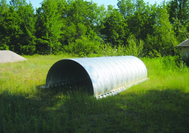
A potential design solution to address both of the issues raised regarding inverts is to remove the invert altogether by using a bottomless culvert (see Figure 3). Steel and aluminum structural plate structures as well as precast concrete structures are all available in geometries with and without inverts. Along with eliminating a potential maintenance issue, bottomless culverts also have less impact on the stream, so they’re considered more environmentally friendly options.
Figure 3. Open Bottom Corrugated Steel Pipe (CSP), before and after installation.
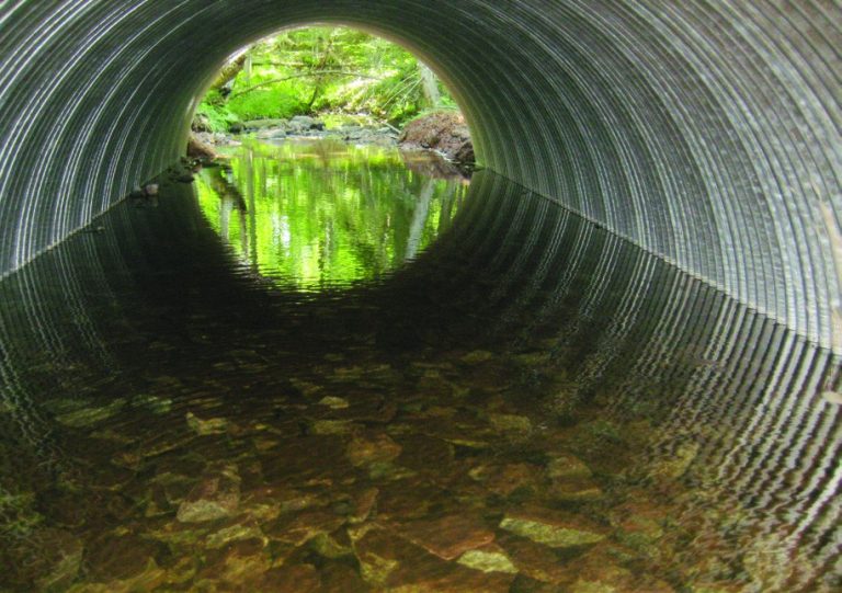
In some environments, it also may be advantageous to design the foundation so the invert of the arch structure is above the five-year flow-event elevation. This raises the structure so it’s only impacted by infrequent flow events, thereby limiting its exposure to potential corrosion and abrasive elements from the stream flow. This can be accomplished by raising the elevation of the top of the strip footing the structure sits upon, and it can be a practical solution for structures with fairly narrow strip footings. For structures with wider footings, a pedestal wall can be incorporated to raise the structure to the desired elevation (see Figure 4).
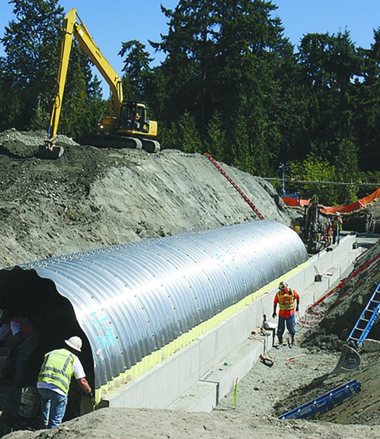
Figure 4. Plate structure on a pedestal wall with coated invert plates.
Alternatively, rather than removing the invert, additional protection for the invert can be designed into the initial installation. If abrasion is a concern due to a high bedload or velocities, choose a structure geometry that allows the invert to be installed below the flowline. For culvert pipes, the structure size can be increased slightly and the invert lowered below the flowline of the waterway enclosed by the pipe. The invert can be filled with compacted soil, rip rap or other countermeasures to protect it from abrasion. In many cases, the pipes can be left to silt in on their own.
Another advantage to this approach is that the structure’s flow profile is enhanced with a buried invert, because the first few inches of rise in a structure with an invert provide very little in terms of available flow area. By burying the invert, the available flow area within the structure’s lower portion is significantly increased; thereby accommodating normal flows at lower flowline elevations. For instance, if a location required a 66” diameter pipe to accommodate the flows it would receive, a 72” diameter pipe buried by 6” would provide many advantages. First, even with the invert buried by 6”, the available end area for the culvert would increase by 3.4 square feet or 14 percent. The available flow area within the lower 6” of the culvert would increase by 83 percent while protecting the bottom 39” (55 percent) of culvert width. The increase in cost of the larger-diameter pipe is small when compared to the significant benefits derived in increased service life and hydraulics by incorporating this technique.
Rather than burying the pipe invert, another design concept would be to install a concrete pavement to cover the invert to protect it from abrasive forces (see Figure 5). The paved invert generally can be added with little impact to the flow characteristics—it normally doesn’t require oversizing the culvert. In highly abrasive environments, however, a paved invert can increase the culvert’s service life by 25 years or more.
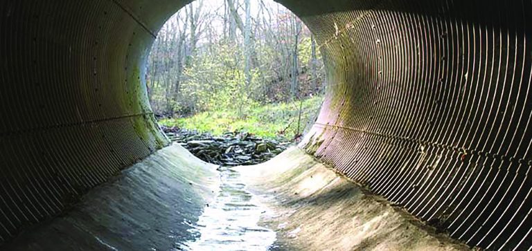
Figure 5. A concrete paved invert can provide added protection against abrasive forces.
For steel or aluminum structural plate structures, the invert plate thicknesses can be increased to allow for some additional sacrificial wall thickness. Polymer coatings also can be applied to structural plate structures to provide additional protection from abrasion and corrosion. The coatings can be applied to the invert plates and brought up the sides of the structure to an elevation equivalent to a five-year storm event. All of these items would significantly delay maintenance and extend the service life of the culvert structures.
Finally, one other design consideration to take into account regarding the service life of buried structures is the backfill used around the structure. Although the primary function of the backfill is to provide load dissipation and passive support to the buried bridge structure, the backfill material used also can affect the structure’s service life.
In general, free-draining backfill materials are preferable as they allow water to pass through them freely, thereby constantly rinsing the structure’s surface of any chlorides or other corrosive elements that may be carried to the structure from surface water or runoff. In addition, for aluminum structures, a free-draining backfill assures a consistent source of oxygen that allows the passive aluminum-oxide protective layer to continually exist at the surface of the material, thus inhibiting corrosion. Backfill materials known to have chemical components that may create a pH outside the recommended range for materials used in the structure also should be avoided. Recycled concrete materials and backfills with a significant amount of fly ash can sometimes create this chemical imbalance and potentially increase the rate of corrosion for the bridge structure. In addition, recycled concrete can contain reinforcing fragments that can be sources of dissimilar metal corrosion when used around aluminum structures. Recycled concrete materials also should be tested to establish whether or not they have sufficient resilience to deterioration during handling, placement and compaction. An abrasion test should be performed to make sure the material gradation doesn’t change significantly during normal construction activities.
These are some design elements that should be considered when buried bridge structures are being used. These structures provide great utility and value under any circumstance, but with some additional consideration, their service lives can be extended to 100 years or longer.
Online quiz for this article is not active and
PDH credit is no longer available.
This article is being maintained for informational purposes only.